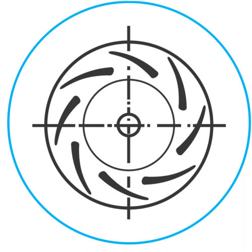
SYMBIOSIS Backward Curved Aerofoil Blades
Backward curved Aerofoil has ideal Aerodynamic characteristics with maximum Design efficiency of up to 89%. It can be used for clean air or low dust concentrations for medium to high-pressure industrial applications. 4 different series for varying wheel designs allow flexibility in selection.
The double-skin airfoil makes the blades sensitive to abrasive dust and is to be used only for low dust loads.
SYMBIOSIS MOST POPULAR MODELS FOR BACKWARD CURVED AEROFOIL BLADES
With years of application-oriented experience and latest Manufacturing facilities, we manufacture these Impellers within close tolerances matching exact blade profiles using mechanized welding procedures. With welding distortion Management, maintaining minimal impeller run out before dynamic balancing and with special handling of Impeller, SYMBIOSIS delivers world class fans and blowers for your Critical applications.
Our Blowers are truly SYMBIOTIC to your process. Think of Air…… Think of SYMBIOSIS Blower.
We offer the Airofoil centrifugal fan in multiple sizes, arrangements, construction classes, impeller and housing widths. Whether standard or custom, each SYMBIOSIS Industrial Fan is designed and built with unmatched quality and backed by responsive service.
AEROFOIL FAN PERFORMANCE & DESIGN
- Air volumes up to 9,50,000CMH
- Static pressures up to 1500 mmWC
- Temperatures up to 550 ℃
- High Peak Total Efficiency up to 89%
- Non-overloading power curve.
- Single Width, Single Inlet (SWSI) and Double Width, Double Inlet (DWDI).
- Silent in operation viz z viz other profiles for similar operation.
- Very high Strength of Impeller for clean gas application viz a viz other profiles for similar operation.
Arrangement of Drive
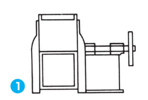
ARRANGEMENT NO. 1 SWSI
Wheel overhung. Bearing in bracket supported by fan housing. For beit drive or direct connection.
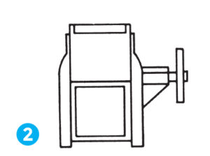
ARRANGEMENT NO. 2 SWSI
For belt drive or direct connection. Wheel overhung. Bearing in bracket supported by fan housing
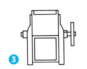
ARRANGEMENT NO.3 SWSI AND DWDI
For belt drive or direct connection. One bearing on each side and supported by fan housing.
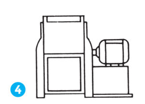
ARRANGEMENT NO. 4 SWSI
For direct drive. Wheel overhung on motor shaft. No bearing on fan. Base mounted or an integrally direct connected motor.
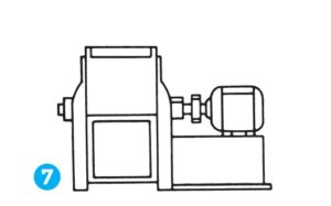
ARRANGEMENT NO.7 SWSI AND DWDI
For belt drive or direct connection. Arrangement No.3 plus base for motor.
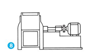
ARRANGEMENT NO.8 SWSI
For belt drive or direct connection. Arrangement No.1 plus base for motor.

ARRANGMENT NO.9 SWSI
For belt drive Arrangement No.1 designed for mounting prime mover on side of base.
Direction of Rotation And Discharge
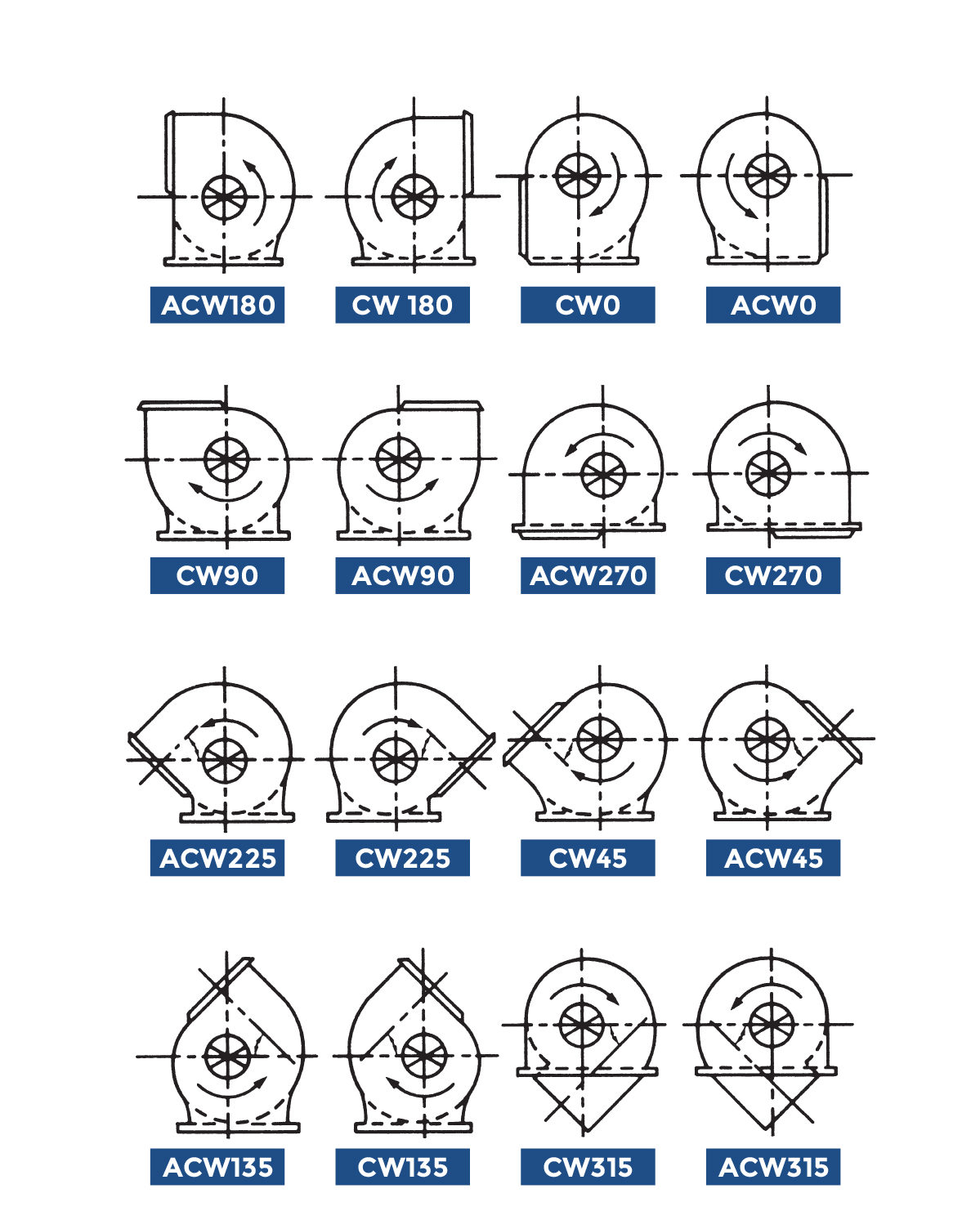
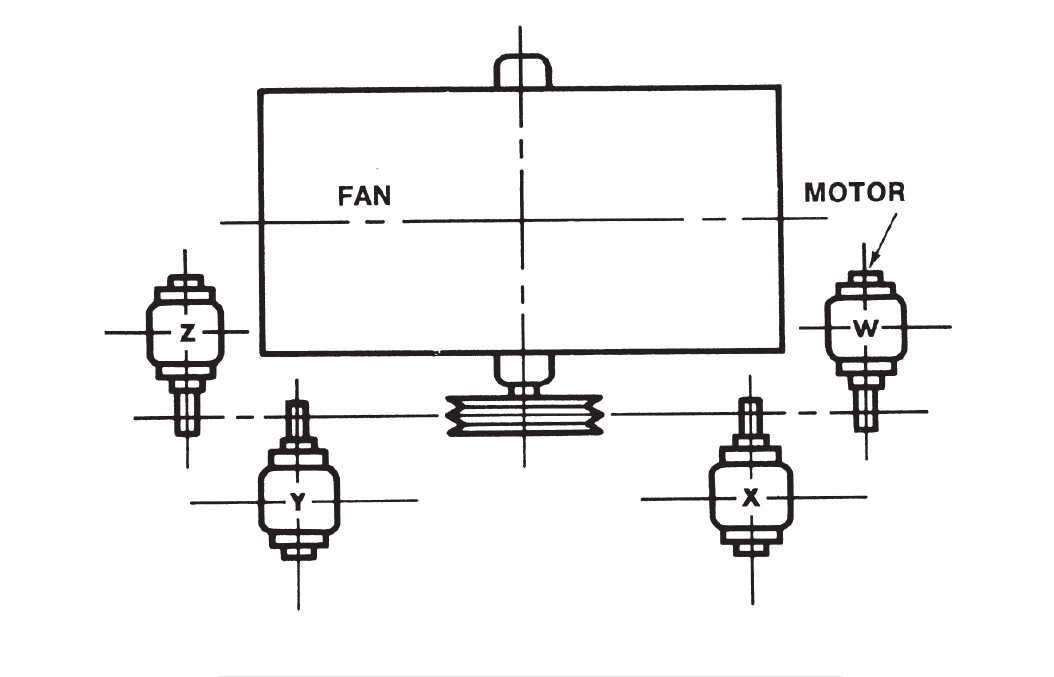
Standard Motor Position
